
 RUS
RUSSubaru Lineartronic TR690: no major problems!
 Lineartronic brand name is used for two Subaru transmissions – TR690 and TR580. The same operating principle is applied in both transmissions: gear ratio is changed by CVT with chain on conic pulleys. To extend the range of ratios and ensure smooth start, a hydraulic torque converter is applied.
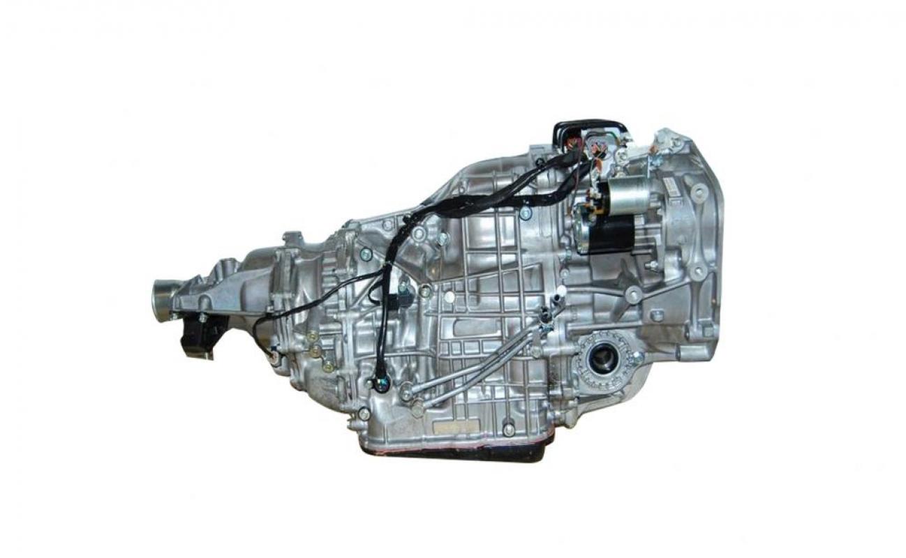
However, there are some major differences between the transmissions, e.g. TR690 valve body is located on the bottom of transmission (Fig. 1) as compared to TR580’s on the top. Starting in May 2009, TR690 has been used in Subaru Outback 2.5 l models. Lineartronic TR580 was mounted in various models equipped with 1.6 l - 2.0 l engines. From September 2014, it was replaced with modified TR580 transmission in Outback 2.5 l gasoline-powered models. TR690 CVT was also modified to extend the transmitted torque; new version is called HCVT and is currently mounted in the most powerful Subaru Outback models based on six-cylinder 3.6 l gasoline and diesel (not supplied to Russia) engines, earlier equipped with hydromechanical transmission. TR690 HCVT is also used in Forester 2.0XT with turbocharging and WRX STI. As from 2014, all other Subaru models available in Russia have been equipped with TR580 transmission.
Power flow is transferred from input shaft through input transfer gear group to input clutch actuating the driving pulley. The driven pulley is followed by plane-tary reduction gear, which is used to select the driving direction, forward or back.
These transmissions do not deliver any major problems if serviced in due time.
TR690: Hydraulic torque converter

 and TR580 (bottom)") However, the transmissions have difficulties with hydraulic torque converter. Technical Information Letter No. 16-90-13 was issued on January 6, 2014 dis-cussing the possibility of applying preventive measures during HTC repair for the solution of problems, which clients complain of, namely, low engine speed during stop. The situation is just about the same as when the car with manual transmission stops with no clutch pedal depressed. The problem is as follows: thrust washer wear inside HTC results in cutting off channel used for depressuri-zation from HTC lockup clutch. Consequently, either late depressurization (short-term engine low idle speed) or no depressurization is made, and engine fi-nally stalls. In our practice of repairing such transmissions we have faced both situations. When repairing HTC, thrust washer must be replaced by thrust needle bearing with preliminary preparation of the bearing seat. Fig. 31 represents the thrust washer to be replaced by the bearing.
However, the transmissions have difficulties with hydraulic torque converter. Technical Information Letter No. 16-90-13 was issued on January 6, 2014 dis-cussing the possibility of applying preventive measures during HTC repair for the solution of problems, which clients complain of, namely, low engine speed during stop. The situation is just about the same as when the car with manual transmission stops with no clutch pedal depressed. The problem is as follows: thrust washer wear inside HTC results in cutting off channel used for depressuri-zation from HTC lockup clutch. Consequently, either late depressurization (short-term engine low idle speed) or no depressurization is made, and engine fi-nally stalls. In our practice of repairing such transmissions we have faced both situations. When repairing HTC, thrust washer must be replaced by thrust needle bearing with preliminary preparation of the bearing seat. Fig. 31 represents the thrust washer to be replaced by the bearing.

 Fuji Heavy Industries commenced the production of modified HTC from October 1, 2013 as part of the transmission No. 633208. The production of modified transmissions with upgraded HTC started from December 31, 2013.
No need to replace
 One more issue relating to TR690 transmission is CVT fluid leak in the junction of engine and transmission. In such case, first one should prepare a new seal for HTC (original part No. 806747020) and remove the transmission to replace it. However, at our enterprise we have repeatedly rectified fluid leak from under the front cover (with seal installed) without replacing this seal. The cover is packed with sealer, and in all such cases the fluid leaks from the same point – between two fastening bolts just under the input transmission shaft. (Fig. 32-34 show flu-id leak points (hashed)
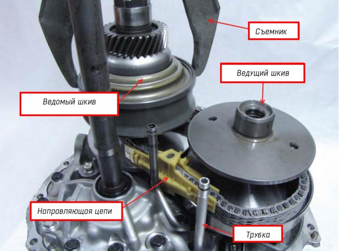
Assembly and disassembly of this transmission is quite simple – just be attentive and accurate. However one should know some other issues (Fig. 20–30).
Be especially careful when mounting hydraulic torque converter to the trans-mission. Do not rock, shake or apply excessive force as there is a major risk of damaging front cover: the cover is broken in the area of the bearing seat support-ing hydraulic torque converter, the same happens to the bearing retainer ring and groove it is mounted in.


Sensor arrangement and diagnostics
 Selector position sensor is located from the right side (Fig. 13). This sensor al-lows starter operation and turns on the reversing lights. It also sends a signal to transmission control module indicating the position of selector lever. Input shaft speed sensor is located under main connectors in the upper part of transmission. It represents a three-wire Hall sensor, which generates a signal based on input transfer gear rotation speed. Secondary pressure sensor is also arranged from the right side (to be described in detail below).
Two electrical connectors in the upper part of transmission connect the electric wiring of transmission with electric wiring of transmission control module.
Black connector – T3. Aggregates selector position sensor contacts and speed sensor signals (Fig. 13 и 14).
Grey connector – Т4, for solenoids of the transmission and temperature sensor (Fig. 13 and 15).


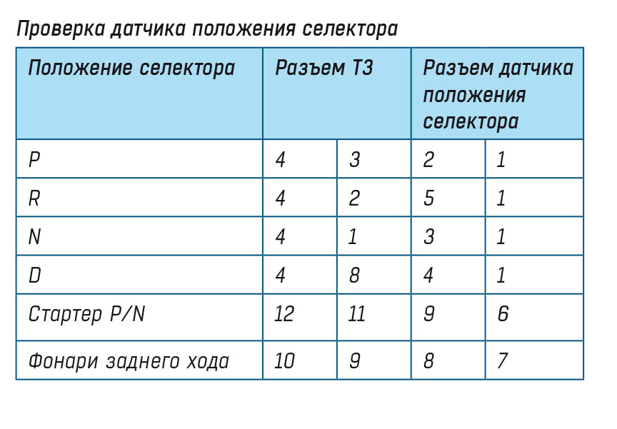


Fig. 14 and tables below show all information required to test the selector posi-tion sensor and speed sensors right on the car.
To test the transmission temperature, connect tester to pins 16 and 19 of Т4 con-nector. At 20°С resistance must be 2.5 kOhm, and 330 Ohm at 80°С.
 Speed sensors and pressure measurement port in AWD system are arranged on transmission from the left side (Fig.16). All speed sensors are three-pin and have general ground and power supply. 5 V signal is generated on middle contact (rep-resented on diagram as rectangular pulse signal). Output shaft speed sensor mon-itors driven pulley rotation speed. Sensory element is the gear mounted on driven pulley.
Secondary pressure sensor (Fig. 13 and 17) measures secondary pressure or, as we call it, line pressure. Pin 1 – power supply (5 V), pin 3 – ground, pin 2 – sig-nal to transmission control module. Voltage at signal wire varies from 0.5V at no pressure up to 4.5 V at maximum pressure.


Line pressure testing
When problem occurs in any of these modules, always begin with checking fluid level. If level is normal, check the secondary (line) pressure. Secondary pressure port is located from the left side under the secondary pressure sensor (Fig. 13).
In this transmission pressure can reach high values, so you will need a special pressure gauge and hose suitable for pressure up to 1000 psi (69 bar).
Special tool for Subaru pressure gauge No. 18801АА000, and No. 18681AA010 for adaptor. If you want to make your own adaptor, use plug thread size 18х1.5 mm.
During pressure testing compare readings from your scanner with actual pressure readings on pressure gauge. If readings differ widely, check power supply and ground of secondary pressure sensor. If power supply voltage is normal but the signal is wrong, replace the sensor.
To measure pressure readings, set the temperature in transmission between 60 and 80°С. In positions P and N with closed throttle (at idle) normal pressure must be within the limits of 72–218 psi (4.96–15 bar).
In D and R positions, during stall tests pressure must be within the limits of 652–870 psi (45–60 bar).
Pressure testing in AWD system
If car vibrates on turns or torque is not transmitted to rear wheels, check pressure in AWD system port.
Subaru has special tools for pressure measurement:
- 34009АС010 adaptor A
- 34099АС020 adaptor B
- 18681AA000 pressure gauge adaptor
- 4985754000 pressure gauge.
If you want to make your own adaptor, use plug thread size 13х1.5 mm.
Pressure in unloaded AWD system must be zero. When signal from AWD sole-noid AWD is rising, pressure also increases. Under 60% load, pressure must be 58–102 psi (4–7 bar), and under 95–100% must reach 145–174 psi (10–12 bar). In P and N positions, pressure must be zero at closed throttle.
Some scanners has FWD test mode. In this mode, AWD system is disabled and normal pressure must be zero.
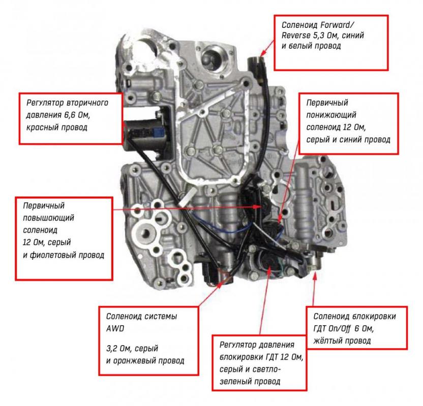
Let us examine the disassembled valve body.
All power supply solenoids are controlled by “+” wire from transmission control module and have general ground on valve body. Secondary pressure controller and Forward/Reverse solenoid are linear-type solenoids. HTC lockup pressure controller, primary up and primary down solenoids and AWD system solenoids are controlled by pulse-wide modulation (PWM). All solenoids are normally closed. HTC lockup solenoid On/Off is the only solenoid operating based on ON/OFF principle is also normally closed.
Manufacturer does not distribute solenoids individually – only the assembled valve body. Replacement cost is sufficiently high. However, as practice shows, in most cases solenoids can be repaired. We disassemble solenoid, rewind a wind-ing, check resistance and operability then assemble again. Thus we reduce client’s costs several times.